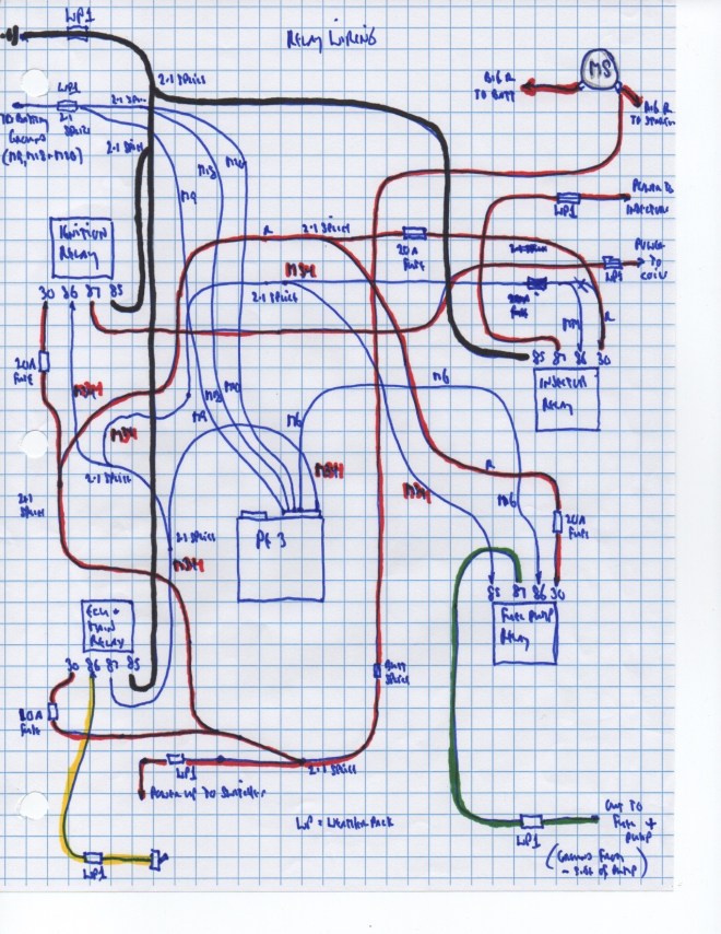
I found that trying to follow the factory diagrams was miserably difficult. Started doing my own drawings to help me visualize component placement and routings. The drawing above represents the interrelationship of the PE-3 and the required relays.
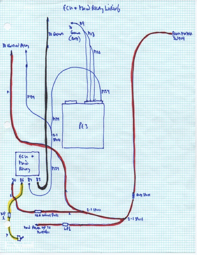
I found that I needed to simplify things even further so started doing drawings of each individual relay. Above is the drawing for the ECU and Main Relay. The “M” numbers represent the wire coming from the specific pin on the ECU. And, fortunately, the PE-3 fully populated Main Connector comes with wires numbered for their entire lengths with the corresponding numbers. The “WP” references pertain to where I thought I might need to install Weather Pack easy-to-disconnect connectors.
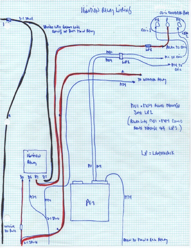
Ignition relay wiring drawing. The pin numbers below the Ignition Relay box are the pin numbers actually printed on most basic relays. Had a difficult time understanding how they worked until stumbling across a couple of YouTube videos.
Power comes out of Pin 87 on the relay up to the center terminal on the ovaloid connector port of the coil. PE-3 Pin M01 is the signal wire for coil 1 (the terminal to the left) while Pin M04 is the signal wire for coil 2 (the terminal to the right of center on the connector port.
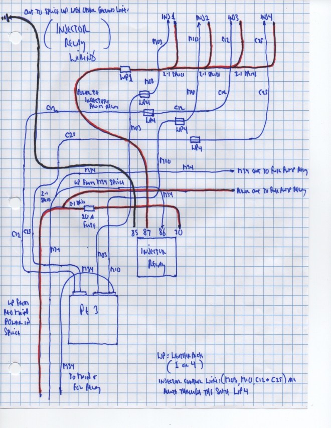
Next in the sequence was the Injector Relay. A single power line comes up from Pin 87 on the relay and is then spliced to provide power to all four injectors via the red wire of each injector’s pigtail. Each individual injector is controlled by a single wire coming from its specific PE-3 pin and then on to connect to the black wire of each injector’s pigtail. Injector 1 is controlled by PE-3 Main Connector pin M03. Injector 2 is controlled by M10. Injector 3 is controlled by C12 from the Comm Connector. Injector 4 is controlled by C25.
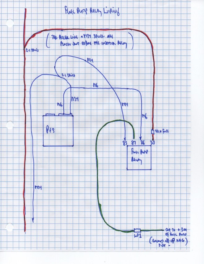
The last relay in the sequence (at least as I visualized it) was the Fuel Pump Relay. This relay did not require a ground wire in that the grounding function occurred at the pump.
Performance Electronics recommends that each relay be protected by a fuse from the power coming into the relay (via the 30 pin). I first used in-line fuse holders simply because it was easier for me to visualize the flow of current. Ultimately changed over to relays that had an integral fuse to save space. From Del City in Milwaukee, Wisconsin. $20.49 each.
Next Chapter: Preparing for the Wiring Process
