The injectors were next up in the wiring sequence. The connectors for the stock Ford injectors were the readily available Bosch type EV1. I ordered EV1s with pigtails already in place to, once again, simplify my visualization and installation processes. Connectors Fast in Meridian, Idaho had pig-tailed EV1s for $6.50 each. Ordered several in that EV1s are used on the Cam Sensor, the Air Temp sensor, the Oil Temp sensor and the Crank sensor as well as the Injectors.

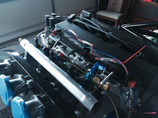
Injector wiring diagram. Power comes into the injectors on the red wire side. That red (power) wire starts at Pin 87 on the Injector Relay and then is spliced to provide power to each injector. The injectors are controlled via the black wire side of each connector. M03 controls injector one. M10 controls injector two. C12 (off of the Comm Connector) controls injector three. C25 controls injector four. Once again, those letters and numbers running the full length of the wires coming from the Main and Comm Connectors, are very helpful in assuring that the correct wire is going to the right place.
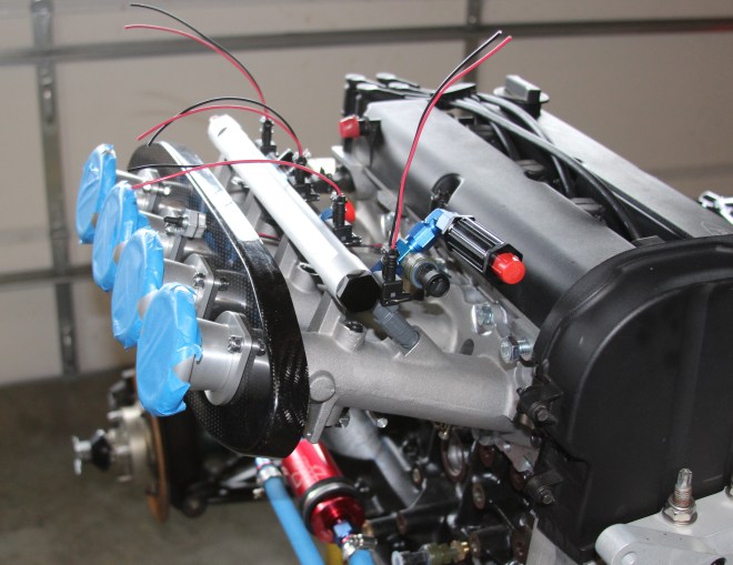
Injectors wired up, splices in place and the “write-on” heat shrink written on so as to designate correct connector/injector correlation. The clear multi wire splice heat shrink tubing butt connectors are seen here performing their splicing function. Color coded crimp location indicators also visible. And, very faintly, one of the wire number indicators can be seen on the blue wire just above the 2 to 1 splice connector for the number two injector.
